Engineers in automotive R&D, technology planners, tier-1 supplier specialists, and mobility analysts usually know their own components inside out. A body engineer knows the martensitic phase transformation of a hot-stamped B-pillar. A chassis engineer knows the compliance matrix of a hydro-bushing or the rack force limits of a belt-driven R-MDPS. A power electronics engineer knows the switching loss curves of a Silicon Carbide (SiC) MOSFET module. Yet when these specialists sit in the same vehicle packaging meeting, organizational silos show up immediately. Few engineers can map the exact mechanical hardpoints, structural load paths, cooling manifolds, and CAN-FD/Ethernet control frames that bind their part to the neighboring department’s subsystem.
Most public references treat vehicle architecture using an outdated internal-combustion dichotomy: the body as a sheet-metal shell and the chassis as a rolling frame carrying an engine, transmission, and suspension. That mental model fails on modern dedicated electric vehicles. Reducing the body domain to the welded sheet metal (BIW) ignores how closures, exterior aerodynamic actuators, and interior structural beams govern wind noise, cooling drag, and occupant restraint. Separating the electrification domain from the underbody and chassis hides the reality of modern skateboard platforms, where the high-voltage battery pack acts as a primary structural shear panel and the traction motor directly alters wheel slip, pitch attitude, and hydraulic braking pressure.
Core Architectural Definition
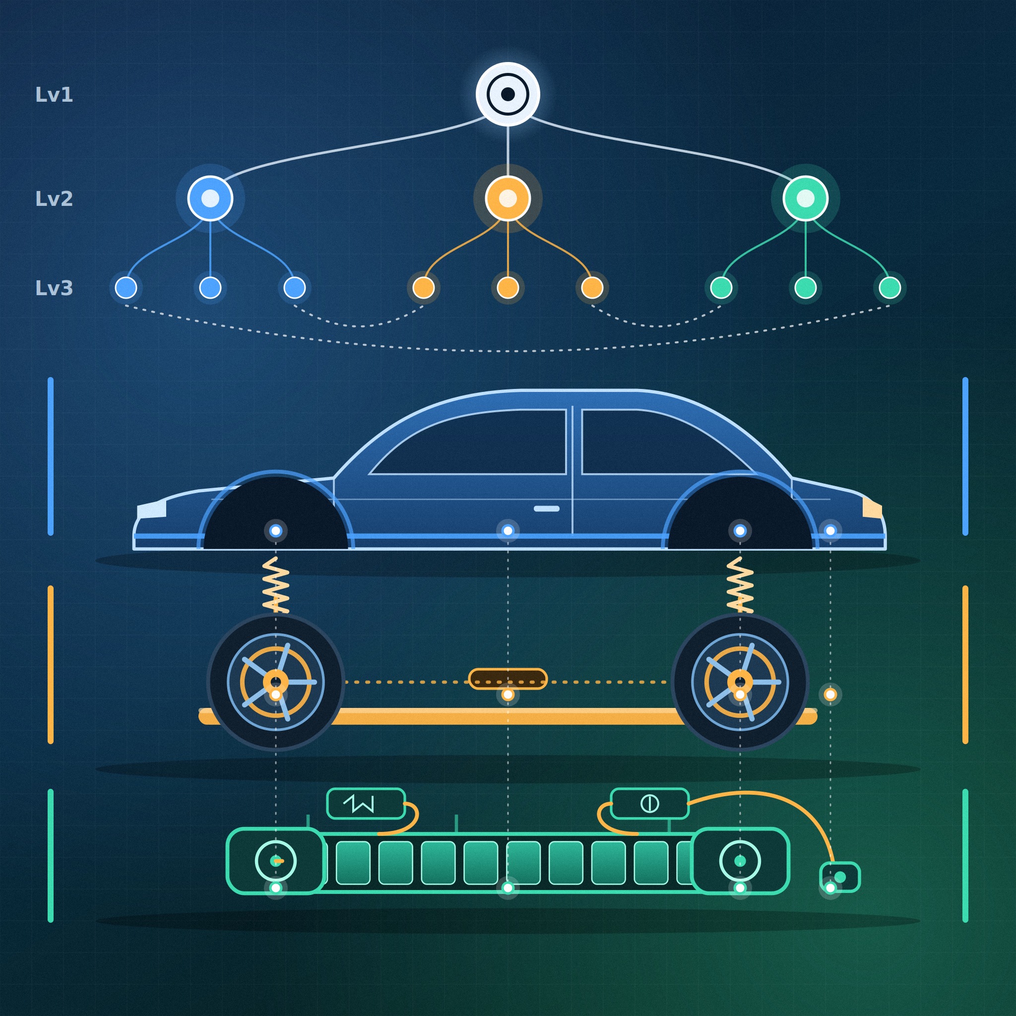
Modern electric vehicle architecture divides into three Level 1 domains: the Body (occupant cell, crash energy dissipation, aerodynamics, and acoustic isolation), the Chassis (six-degree-of-freedom ground force control, ride isolation, steering, and deceleration), and Electrification (high-voltage energy storage, 3-phase power conversion, propulsion torque, and thermal regulation). In a skateboard platform, Cell-to-Body (CTB) or Cell-to-Chassis (CTC) integration merges the battery enclosure into the underbody load path, while electric Vehicle Motion Control (e-VMC) couples traction inverters directly with electro-hydraulic braking and active suspension dampers.
This technical reference decomposes a complete vehicle across three Level 1 domains, twelve Level 2 subsystems, and over sixty Level 3 assemblies and components, matching the Bill of Materials (BOM) and R&D division structures used by global OEMs. After breaking down each domain from the top down, we examine the bottom-up physical, electrical, and thermal interfaces where engineering trade-offs happen.
1. Level 1 & Level 2 Master View: From ICE Unibody to Skateboard Platform
In a traditional internal combustion engine (ICE) unibody vehicle, the front compartment houses a heavy cast-iron or aluminum engine block and multi-speed transmission, while a central exhaust and propeller shaft tunnel cuts through the cabin floor. Dedicated electric skateboard platforms reorganize this spatial packaging into three distinct zones: a compact front overhang housing the front e-Axle, steering rack, and HVAC/thermal module; a flat, long-wheelbase underfloor housing the structural high-voltage battery pack between the axles; and a rear overhang housing the primary rear e-Axle and multi-link subframe.
Placing a 450 kg to 650 kg battery pack directly beneath the cabin floor drops the vehicle’s center of gravity (CoG) by 100 mm to 150 mm compared to an equivalent ICE crossover and pushes the static front-to-rear weight distribution toward a neutral 50:50 balance. At the same time, concentrating mass between the wheel centers alters the polar moment of inertia in yaw, pitch, and roll, forcing structural changes across all twelve Level 2 subsystems.
Before examining the mechanics of each subsystem, the master table below organizes the entire vehicle BOM hierarchy from Level 1 domains down to Level 3 components, specifying the target physical metrics and cross-domain connections for every group.
| Lv1 Domain | Lv2 Subsystem (12) | Lv3 Key Assemblies & Components (60+) | Engineering Function & Target Metrics | Cross-Domain Interface |
|---|---|---|---|---|
| 1. Body System | 1.1 Body Structure (BIW) | Dash panel, Front/Center/Rear floor, Side sill (Rocker), A/B/C pillars, Roof rail & bow, Front side member, Fender apron/upper member, Crash box, Bumper back beam | Torsional stiffness (>35,000 N·m/deg), local hardpoint dynamic stiffness (N/mm), 3-way crash load distribution (Mild 270 MPa to Hot Stamping 1,500 MPa) | Bolts to HV Battery Pack frame (CTB) and Front/Rear Subframes |
| 1.2 Closures | Hood, Front/Rear doors (Outer/Inner hemming panels), Tailgate, Door impact beam, Hinges, Check arm, Latch & striker, Power spindle drive, Triple weatherstrips | Side pole intrusion resistance, swing kinematics, dent resistance (bake-hardening steel/Al), wind noise & water sealing | Transfers side impact load into BIW B-pillar, Side Sill, and Battery cross-members | |
| 1.3 Exterior | Front/Rear bumper fascia & energy absorber foam, Active Air Flap (AAF), Fenders, Rocker garnish, Roof spoiler, LED Headlamp/RCL, Acoustic windshield, Flush glass | Aerodynamic drag reduction (Cd 0.21–0.26), pedestrian lower-leg protection, high-speed lift balance | AAF actuator controlled by ITMS ECU; wheelhouse flow alters Chassis lift & brake cooling | |
| 1.4 Interior | Cockpit module (IP), Cross Car Beam (CCB), Center console, Seat frame & foam pad, Seatbelt pretensioner, PAB/SAB/CAB airbags, Headlining, PU foam floor carpet | Lateral cowl reinforcement, steering column natural frequency (>35 Hz), occupant restraint, high-frequency acoustic absorption | CCB mounts Chassis steering column & HVAC module; floor carpet damps battery/road noise | |
| 2. Chassis System | 2.1 Suspension | Coil/Air springs, Shock absorbers (ECS variable dampers), Forged Al lower/upper control arms, 5-Link rear arms, Knuckle (Carrier), Stabilizer bar & link, Hydro-bushings | Vertical load support (+300–500 kg EV mass), K&C camber/toe compliance control, roll gradient, pitch/bounce isolation | Strut tower & arm loads feed into BIW; ECS coordinates with PE motor pitch control |
| 2.2 Steering | Steering wheel & column, Intermediate shaft (U-joint), Rack-and-pinion gear, R-MDPS (belt & ball-nut), Inner/Outer tie rods, Rear Wheel Steering (RWS), SbW (SFA/RWA) | High rack thrust capacity (12–18 kN), yaw response linearity, minimum turning radius reduction, ADAS lane-keeping precision | Powered by 12V LDC output; mounted on Front/Rear Subframes and Interior CCB | |
| 2.3 Braking | Brake pedal, Integrated Electric Booster (IEB/IDB with pedal simulator), Brake lines, Fixed/Floating calipers, Low-dust pads, Vented discs, Moc-EPB, Dry EMB | Vacuum-independent pressure build-up (<150 ms to locking), seamless regenerative/friction blending, thermal fade resistance | IEB exchanges real-time torque commands with VCU/Inverter over CAN-FD for regen blending | |
| 2.4 Subframe & Tire | Front H/Perimeter subframe, Rear 5-Link cradle, Subframe hydro-mounts, Gen-3 wheel hub bearings, Aero alloy wheels, High-load HL acoustic-foam EV tires | Two-stage road noise isolation (50–300 Hz), unsprung mass minimization, high vertical load capacity & low rolling resistance (RRC) | Carries PE e-Axle torque reaction mounts; forms lower frontal crash path into BIW | |
| 3. Electrification | 3.1 PE System (e-Axle) | SiC MOSFET Inverter (DC-Link cap, gate driver), Hairpin IPM motor (oil-cooled stator/rotor), Reduction gear & differential, Disconnector (DAS), CV driveshafts | High-speed rotation (15,000–21,000+ rpm), >97% inverter efficiency, 10 ms torque response, zero drag loss during AWD coasting | Mounts to Chassis Subframe; drives Chassis hub via driveshaft; executes e-VMC slip/pitch control |
| 3.2 HV Battery System | Pouch/Prismatic/Cylindrical cells, Cell-to-Pack/Body (CTP/CTB) array, BMS, BDU (Main contactors, pre-charge resistor, pyro-fuse), Cooling plate, Extruded Al case | Gravimetric/volumetric energy density, SOC/SOH estimation, <2 ms arc-free short-circuit isolation via pyro-fuse, shear stiffness | Structural shear floor for BIW underbody; triggered by Body Airbag ACU during crash | |
| 3.3 Charging (ICCU) | Integrated Charging Control Unit (Bidirectional OBC + 12V LDC + V2L/V2G inverter), CCS Combo inlet, Rear motor/inverter 400V-to-800V multi-charging circuit | 11–22 kW AC charging, 350 kW 800V DC ultra-fast charging (10–80% in <18 min), 3.6 kW V2L AC output, 12V auxiliary bus supply | LDC feeds 12V power to Chassis R-MDPS, IEB, ECS, and Body BCM/Lighting controllers | |
| 3.4 Thermal (ITMS) | Electric compressor, Water-cooled condenser, Refrigerant chiller, Multi-way Coolant Control Valve (CCV), Electric water pumps (EWP), Radiators, HV PTC heater | Battery window (15–35°C), PE window (<60–80°C), waste-heat scavenging heat pump COP optimization for winter range retention | Commands Body Exterior AAF opening; connects to Interior HVAC evaporator/heater core |
2. Domain 1: Body System — Structural Mechanics, Closures, Aero, and NVH (Lv2 to Lv3)
Treating the vehicle body as nothing more than a stamped steel frame misses three-quarters of body engineering. A complete Body Domain comprises four Level 2 subsystems working together: Body Structure (BIW) for static/dynamic stiffness and crash survival, Closures for access kinematics and weather sealing, Exterior for aerodynamic flow control and pedestrian impact management, and Interior for cockpit structural support, occupant restraint, and acoustic absorption.
2.1 Body Structure (BIW, Body in White)
The Body in White is the welded, bonded, and riveted metal skeleton prior to painting and trim assembly. It divides into the Underbody (dash panel, front floor, center floor, rear floor, and left/right side sills or rockers), the Upper Body (A-pillar, B-pillar, C-pillar, roof side rails, roof bows, cowl panel, and rear quarter panels), and the Front/Rear End Structures (bumper back beam, crash boxes, front side members, and fender apron upper members).
To pass severe crash regulations—specifically the IIHS small overlap frontal test (25% width impact at 64 km/h against a rigid barrier) and the updated IIHS side impact test (a 1,900 kg movable deformable barrier striking at 60 km/h)—BIW engineers design a 3-Way Multi-Load Path alongside a graded tensile-strength metallurgy map:
- Upper Load Path: Impact forces bypassing the main longitudinal rails in a small overlap collision are caught by the fender apron upper member and directed into the A-pillar and roof side rail.
- Middle Load Path: The bumper back beam and extruded aluminum or steel crash boxes deform plastically first, transferring remaining kinetic energy down the main front side members. At the dash panel base, a bifurcated torque box splits the load into the side sill (rocker) and the center floor cross-members.
- Lower Load Path: The front subframe (cradle) absorbs lower frontal impact forces and channels them into the lower floor rails and the forward mounting flange of the high-voltage battery pack frame.
2.2 Closures (Hanging & Opening Assemblies)
Closures include the hood, front and rear side doors, and the tailgate or trunk lid. Each closure assembly joins a stamped outer skin panel (designed with bake-hardening steel or 6000-series aluminum for dent resistance) to an inner structural panel using perimeter roller hemming and high-strength structural epoxy adhesive to prevent panel flutter.
Inside the door cavity, a 1,500 MPa tubular or hat-section Door Impact Beam spans between the front hinge reinforcement and the rear latch reinforcement to resist side intrusion before the B-pillar and rocker sill engage. Kinematic hardware—cast or forged hinges, stepped check arms that hold the door open on grades, cinching latches with forged strikers, and motorized tailgate spindle drives—governs opening effort and closing sound quality. Around the perimeter, multi-bulb EPDM rubber weatherstrips (primary door seal, secondary body-mounted aperture seal, and lower rocker dust seal) maintain cabin pressure and block high-frequency wind noise (500–4,000 Hz), which becomes highly noticeable in an EV without engine masking noise.
2.3 Exterior (Aerodynamics & Pedestrian Protection)
The Exterior subsystem shapes the vehicle’s aerodynamic envelope and manages low-speed impact energy. Front and rear bumper fascias (injection-molded polypropylene/EPDM blends) house multi-density expanded polypropylene (EPP) energy-absorbing foams and lower leg stiffeners engineered to control tibia bending moments and knee shear displacements during pedestrian impacts. Above or inside the lower bumper intake sits the Active Air Flap (AAF) mechanism. Driven by a stepper actuator linked to the thermal management controller, the AAF keeps louvers closed during highway cruising to cut aerodynamic drag (Cd reduction of 0.008 to 0.015), and opens them only when condenser or radiator heat rejection demands airflow. Flush door handles, aero wheel air curtains, full-length underbody shields, rear roof spoilers with sharp trailing edges for flow separation, and acoustic PVB-interlayer laminated windshields complete the exterior package.
2.4 Interior (Cockpit Structure, Restraints & Acoustic Trim)
Beneath the soft-touch skin of the Instrument Panel (IP / Cockpit Module) runs a major structural beam: the Cross Car Beam (CCB), also called the cowl crossbar. Fabricated from variable-gauge hydroformed steel tubing or die-cast magnesium alloy, the CCB bolts directly between the left and right BIW A-pillars. It provides lateral body stiffness, supports the heavy steering column to keep its natural resonant frequency above 35–40 Hz (preventing steering wheel shake at idle or over washboard roads), and absorbs knee-bolster loads during a frontal crash. The seat system integrates a high-strength steel frame, dual-stage seatbelt pretensioners with load limiters, and side torso/far-side airbags. Across the floor pan, a heavy-layer acoustic carpet backed with decoupler polyurethane (PU) foam and fibrous felt attenuates airborne tire roar and electric motor high-frequency whine (order noise from gear meshing and PWM switching at 4–10 kHz).
R&D Design Trade-off: Why Not Build the Entire BIW Out of 1,500 MPa Hot-Stamped Boron Steel?
If 150K hot-stamped steel prevents deformation so effectively, why do engineers still use 270–590 MPa steels and aluminum in the front and rear overhangs? In a collision, a vehicle carrying kinetic energy ($E_k = \frac{1}{2}mv^2$) must dissipate that energy through plastic work ($W = \int F \, dx$) before the deceleration pulse reaches the human body. If the front crash boxes and side member tips were built from ultra-rigid 1,500 MPa martensitic steel without tailored softening, the front end would refuse to buckle, transmitting an extreme deceleration spike ($G$-load) directly into the occupants’ internal organs and brittle-fracturing at spot welds. Therefore, the front and rear zones are engineered as ductile Crumple Zones (using laser-welded tailored blanks and crush initiators that fold in a controlled accordion pattern), whereas the passenger cabin (A/B pillars, roof rail, dash cross-member, and rocker sill) is built as an ultra-rigid Safety Cage using 1,500 MPa hot-stamped steel to preserve survival space and protect the battery pack from mechanical puncture.
3. Domain 2: Chassis System — Ground Force Control and Vehicle Dynamics (Lv2 to Lv3)
While the Body Domain defines the structural container, the Chassis Domain governs every force exchanged between the vehicle and the road surface. Because an electric vehicle carries an extra 300 kg to 500 kg of battery mass compared to an internal-combustion vehicle of the same footprint, the chassis must support higher vertical wheel loads while isolating road harshness and managing combined longitudinal and lateral forces within the tire’s friction circle.
3.1 Suspension System (Kinematics & Compliance)
An automotive wheel assembly has six degrees of freedom (translations along X, Y, Z and rotations in Roll, Pitch, Yaw). The suspension linkage constrains five of those degrees of freedom so the wheel can move primarily along its vertical Z-axis stroke (jounce/bounce and rebound). Most compact-to-midsize EVs pair a front MacPherson strut (or virtual-kingpin double wishbone on premium platforms) with a rear 5-Link Multi-Link Suspension. Separating the rear suspension into five individual links (upper front, upper rear camber link, lower front, lower rear spring link, and toe control link) allows chassis engineers to place the virtual instant center outside the physical wheel packaging. This geometry generates progressive negative camber gain during body roll to keep the outer tire tread flat against the asphalt, while inducing slight toe-in under braking and cornering side forces to stabilize the rear axle.
Springs (helical steel coil springs or multi-chamber air springs) support the static sprung mass, while shock absorbers dissipate kinetic oscillation energy into heat via hydraulic valving. Electronically Controlled Suspension (ECS) dampers use proportional solenoid valves—or magnetorheological fluid—to adjust damping forces every 2 to 5 milliseconds based on wheel vertical accelerometers and body gyroscopes. All suspension links converge at the Knuckle (Wheel Carrier), typically cast or forged from aluminum alloy to reduce unsprung mass. At the inner pivot points, Hydro-bushings (fluid-filled elastomeric mounts) provide asymmetric stiffness: high radial stiffness for sharp steering response and low axial/rotational stiffness with internal glycol fluid damping to absorb sharp longitudinal impacts over expansion joints.
3.2 Steering System (R-MDPS, RWS, and Steer-by-Wire)
The mechanical steering chain runs from the steering wheel and collapsible energy-absorbing steering column, through the universal joints of the intermediate shaft, into the rack-and-pinion gear housing, and out through inner and outer tie-rod ball joints to the steering arm on the front knuckle. Whereas small ICE vehicles often use Column-type Motor Driven Power Steering (C-MDPS), heavy EVs and Level 2+/3 autonomous vehicles rely on Rack-type MDPS (R-MDPS). In an R-MDPS unit, a high-output brushless AC motor mounts directly to the rack tube, driving the rack bar via a toothed timing belt and precision recirculating ball-nut mechanism. Applying assistive force directly on the rack eliminates torsional wind-up in the intermediate shaft, delivers rack thrust forces exceeding 12–18 kN for heavy front axles, and provides crisp on-center feedback.
To counteract the 3,000+ mm wheelbases of skateboard platforms, Rear Wheel Steering (RWS) actuators replace the fixed rear toe control links, turning the rear wheels up to 4°–10° opposite the front wheels at low speeds (cutting the turning circle by over 1 meter) and in phase with the front wheels at highway speeds for lane-change stability. Next-generation Steer-by-Wire (SbW) architectures remove the mechanical intermediate shaft altogether, linking a cabin Steering Feel Actuator (SFA) to a dual-redundant Road Wheel Actuator (RWA) over a fault-tolerant CAN-FD/Ethernet backbone to enable variable steering ratios.
3.3 Braking System (IEB/IDB Brake-by-Wire & EMB)
Electric vehicles have no engine intake manifold vacuum to power a conventional vacuum brake booster, and they must blend electric motor regenerative deceleration with hydraulic friction braking without the driver feeling any pedal kickback. The centerpiece of modern EV braking is the Integrated Electric Booster (IEB / IDB)—a single-box Brake-by-Wire unit that merges the master cylinder, vacuum-free electric pressure actuator, pedal feel simulator, and Electronic Stability Control (ESC) hydraulic modulator.
When the driver presses the brake pedal, an isolation cut-valve closes off the hydraulic path to the wheel calipers and diverts brake fluid into an elastic Pedal Feel Simulator, creating a progressive, consistent pedal resistance. Simultaneously, redundant pedal travel sensors read the driver’s deceleration request. The IEB controller requests maximum available regenerative braking torque from the traction inverter; if the driver’s demand exceeds the motor’s regen capacity (or if the battery is at 100% SOC), the IEB’s brushless motor spins a ball-screw plunger to build exact hydraulic pressure in under 150 milliseconds, clamping the brake calipers (multi-piston fixed monobloc or single-piston floating calipers with low-metallic/NAO low-dust pads) onto the vented cast-iron brake discs. On the rear axle, Motor-on-Caliper Electronic Parking Brakes (Moc-EPB) lock the pads mechanically when parked, while upcoming dry Electro-Mechanical Brakes (EMB) replace hydraulic fluid lines entirely with high-speed electric clamping actuators at each corner.
3.4 Subframes, Hubs & EV-Specific Tires
Rather than bolting suspension links, stabilizer bars, steering racks, and high-torque electric motors directly to thin BIW sheet metal, engineers mount them onto rigid perimeter or H-shaped structural cradles: the Front and Rear Subframes. Hydroformed from high-strength steel tubing or cast from aluminum, the subframe bolts to the BIW underbody through four to six large elastomeric or hydraulic mounts, creating a critical two-stage vibration filter. At the ends of the axles, Generation-3 double-row angular contact Wheel Hub Bearings integrate the wheel mounting flange and knuckle bolting flange into a pre-loaded unit. Finally, the wheel assembly contacts the pavement through HL-rated (High Load) EV Tires engineered with reinforced aramid/nylon sidewalls, silica-rich low-rolling-resistance tread compounds, and an interior open-cell polyurethane acoustic foam ring that absorbs cavity resonance noise (around 200–250 Hz).
R&D Design Trade-off: Why EV Tires and Suspension Bushings Experience Accelerated Wear
An electric crossover or sedan routinely weighs 2,100 kg to 2,500 kg—roughly 350 kg heavier than a comparable internal-combustion vehicle—and its electric motor delivers 100% of peak torque (often 350 to 700+ N·m) from 0 rpm within 10 milliseconds. That combination subjects the lower control arm (LCA) compliance bushings, CV driveshafts, and tire contact patches to simultaneous high vertical load ($F_z$) and instant longitudinal shear ($F_x$). If chassis engineers make the LCA hydro-bushings soft to isolate road harshness, the instant motor torque twists the control arm, causing dynamic toe changes (torque steer and wheel hop) that scrub the inner shoulder of the tires. Conversely, stiffening the bushings to lock down wheel alignment transmits 100–250 Hz road booming noise straight into the cabin. Modern EVs resolve this conflict by pairing high-durometer asymmetric hydro-bushings with software-based motor torque-rate shaping during launch and HL-marked (High Load) tires reinforced against sidewall deflection.
4. Domain 3: Electrification System — 800V Power Conversion, e-Axle, and ITMS Thermal Loops (Lv2 to Lv3)
The Electrification Domain stores 400V or 800V high-voltage direct current (DC) energy, converts it into 3-phase alternating current (AC) to generate mechanical propulsion torque, manages bidirectional AC/DC grid charging, and regulates the thermal state of both the electrochemical cells and power semiconductors alongside cabin HVAC.
4.1 Power Electric System (3-in-1 e-Axle & Disconnector)
Modern EVs package the Inverter, Electric Traction Motor, and Reduction Gearbox into a single cast-aluminum housing known as a 3-in-1 e-Axle, eliminating external high-voltage phase cables, reducing mass, and shortening the power path:
- Inverter (Power Module, DC-Link Capacitor, Gate Driver): Switches high-voltage DC from the battery into variable-frequency, variable-voltage 3-phase AC via Pulse Width Modulation (PWM). In 800V architectures, rear primary inverters replace legacy silicon (Si) IGBTs with Silicon Carbide (SiC) MOSFET power modules. Because SiC possesses roughly 10 times the breakdown electric field strength and 3 times the thermal conductivity of silicon, it slashes switching and conduction losses at high voltages, improving system efficiency and extending vehicle driving range by roughly 5%.
- Traction Motor (Hairpin Stator & IPM Rotor): Uses an Interior Permanent Magnet Synchronous Motor (IPMSM) layout where neodymium magnets are embedded inside a laminated silicon-steel rotor in V- or double-layer configurations to harness both magnetic torque and reluctance torque. The stator replaces round copper wire with precision-bent rectangular Hairpin Windings, increasing the copper slot-fill factor above 70% (up from ~45% in round wire). Direct ATF oil-spray cooling over the stator end-windings and through the hollow rotor shaft allows continuous operation at 15,000 to 21,000+ rpm without magnet demagnetization.
- Reduction Gear & Disconnector Actuator System (DAS): A single-speed two-stage helical gearset steps down the motor’s high rpm by a ratio of roughly 8:1 to 11:1, multiplying torque into the open or electronically locked differential and out through constant-velocity (CV) driveshafts. On all-wheel-drive (AWD) vehicles equipped with permanent-magnet motors on both axles, spinning the front motor while coasting induces counter-electromotive force (back-EMF) and iron drag losses. A mechanical dog-clutch Disconnector (DAS) mounted between the differential and the front driveshaft physically decouples the front motor from the rotating wheels in milliseconds during steady highway cruising, boosting real-world efficiency by 4% to 6%.
4.2 High-Voltage Battery System (Cells, CTP/CTB, BMS & BDU)
The battery pack assembles hundreds of lithium-ion cells—pouch, prismatic, or cylindrical (such as 2170 or 4680 formats) using high-nickel NCM/NCMA or LFP chemistries—connected in series and parallel. Traditional Cell-to-Module-to-Pack (MTP) layouts group cells into intermediate aluminum modules before bolting them into the tray. Newer Cell-to-Pack (CTP) and Cell-to-Body (CTB) designs eliminate module housings entirely, bonding cell arrays directly to the pack tray and top cover with thermally conductive structural polyurethane/silicone adhesives to raise volumetric pack efficiency by 15% to 20%.
Two electronic sub-assemblies govern pack safety and power delivery. The Battery Management System (BMS) monitors individual cell voltages, thermistor temperatures, and high-voltage isolation resistance while executing Kalman-filter algorithms to estimate State of Charge (SOC), State of Health (SOH), and maximum allowable charge/discharge power limits. The Battery Disconnect Unit (BDU)—also known as the Power Relay Assembly (PRA)—houses the positive and negative high-voltage main contactors, a pre-charge relay and resistor (which charges the inverter’s DC-Link capacitor gradually at startup to prevent contactor welding from inrush current), a Hall-effect/shunt current sensor, and a pyrotechnic disconnection switch (Pyro-fuse). Upon receiving a crash deployment signal from the body Airbag Control Unit (ACU) or detecting a dead short circuit, the pyro-fuse fires an internal propellant charge that severs the copper busbar in under 2 milliseconds, extinguishing high-voltage arcs before thermal runaway can start. Beneath the cells sits a brazed aluminum Liquid Cooling Plate separated from the cells by a Gap Filler thermal interface material (TIM), shielded underneath by a stamped steel or composite ballistic undercover.
4.3 Charging & Power Conversion System (ICCU & 400V/800V Multi-Charging)
Per the Ohm’s law power relationship ($P = V \times I$) and Joule heating law ($Q = I^2 R t$), doubling the battery architecture from 400V to 800V halves the current required for any given power level and cuts resistive heat dissipation in copper harnesses and connectors to one-quarter. This enables 350 kW ultra-fast charging (10% to 80% SOC in under 18 minutes) using lighter, thinner high-voltage cables.
To consolidate low- and high-voltage power conversion, the Integrated Charging Control Unit (ICCU) combines three components into a single liquid-cooled enclosure mounted beneath the rear seat: a bidirectional On-Board Charger (OBC) that rectifies 11 kW or 22 kW AC grid power into high-voltage DC; a Low-Voltage DC-DC Converter (LDC) that steps 800V down to 12V–14.5V (replacing the ICE alternator) to feed chassis actuators (R-MDPS, IEB, ECS) and body electronics; and a bidirectional inverter that converts HV battery DC back into 110V/220V 60Hz AC (up to 3.6 kW+) for Vehicle-to-Load (V2L) and Vehicle-to-Grid (V2G) operations. Furthermore, when an 800V vehicle plugs into a legacy 400V DC fast charger, the platform avoids adding a heavy, expensive standalone DC-DC boost converter by using its Patent Multi-Charging Topology: incoming 400V DC is routed to the neutral point of the rear traction motor, using the motor’s three phase windings as high-current inductors and the rear SiC inverter’s switches as a boost converter circuit to step 400V up to 800V internally.
4.4 Integrated Thermal Management System (ITMS)
Lithium-ion batteries and power electronics operate in different temperature windows. The HV battery achieves optimal ion diffusivity and lithium-plating-free fast charging between 15°C and 35°C, whereas the PE unit (motor/inverter) and ICCU operate continuously up to 60°C–80°C. The Integrated Thermal Management System (ITMS) couples a high-voltage refrigerant loop with a multi-branch water-glycol coolant loop through two heat exchangers—the Water-Cooled Condenser and the Refrigerant Chiller—alongside a motorized Multi-Way Coolant Control Valve (CCV / Octovalve-class manifold).
During summer 350 kW fast charging or track driving, the CCV isolates the battery coolant loop from the PE radiator loop and routes battery coolant through the Chiller, where expanding R1234yf (or R290/CO2) refrigerant rapidly absorbs heat from the coolant to keep cell temperatures below 40°C. In freezing winter conditions, where internal cell resistance spikes and cabin heating via a resistive High-Voltage PTC Heater can drain 4 to 6 kW of battery power, the ITMS switches into waste-heat recovery mode: the CCV circulates coolant through the warm PE unit (inverter, motor, ICCU) and battery pack, transfers that low-grade thermal energy into the refrigerant via the chiller, compresses the refrigerant through the electric compressor, and releases high-grade heat into the cabin via the water-cooled condenser and interior heater core—achieving a Heat Pump Coefficient of Performance (COP) between 2.5 and 3.5.
R&D Design Trade-off: CTP/CTB Structural Energy Density vs. Collision Serviceability
Eliminating intermediate cell modules in Cell-to-Pack (CTP) and Cell-to-Body (CTB) designs saves 10% to 15% of structural metal mass, increases volumetric cell packing efficiency by up to 20%, and uses thermally conductive polyurethane adhesives to turn the cell array into a monolithic honeycomb core that boosts body torsional stiffness above 40,000 N·m/deg. However, bonding hundreds of cells directly to the pack tray and cooling plate creates a severe post-sale repair trade-off: if a single cell thermistor fails or a road-debris impact dents one corner of the bottom cooling plate, technicians cannot unbolt and swap a single 24-cell module. The entire bonded cell assembly often requires replacement or specialized chemical debonding, driving up insurance collision repair premiums. Consequently, OEMs balance CTB adhesive shear strength against serviceable sub-array partitioning and thicker ballistic underbody shields.
5. System Integration & Cross-Domain Engineering: The 4 Core Interface Scenarios
Understanding individual Level 3 components is only half the task. Vehicle performance, safety, and refinement emerge at the interfaces where the Body, Chassis, and Electrification domains bolt together, exchange heat, and trade control messages every millisecond. Below are the four primary cross-domain coupling scenarios in a modern electric vehicle.
5.1 [Body × Electrification] CTB/CTC Structural Integration and Side-Pole Load Sharing
In early electric conversions, the battery pack hung beneath the floor as dead weight, forcing BIW engineers to thicken the body rails just to carry the payload. In a dedicated skateboard or Cell-to-Body (CTB) platform, the extruded aluminum perimeter frame and internal lateral cross-members of the 450–650 kg HV battery pack bolt rigidly into the BIW rocker sills and floor cross-members via dozens of high-grade M10/M12 shear bolts. The battery pack acts as a massive horizontal Shear Web across the center floor, raising global BIW torsional stiffness by 20% to 35% without adding redundant sheet metal.
During a severe FMVSS 214 / Euro NCAP oblique side-pole impact (where the vehicle slides sideways at 32 km/h into a rigid 254 mm diameter steel pole aligned with the driver’s head and the center of the battery pack), survival depends on a continuous cross-domain load chain: [Closure 1,500 MPa Door Impact Beam (Body) → BIW 1,500 MPa B-Pillar & Side Sill Outer (Body) → Multi-Cell Extruded Aluminum Sill Insert (Body) → Battery Pack Side Mounting Flange & Internal Cross-Members (Electrification)]. The BIW side sill crushes progressively to absorb initial kinetic energy, while the battery case’s internal cross-beams resist the remaining compressive force across the width of the vehicle, preserving a mandatory 25 mm to 40 mm mechanical air gap (clearance zone) between the inner pack wall and the lithium-ion cells so zero cell pouch deformation occurs. Simultaneously, the body Airbag Control Unit (ACU) sends a hardwired PWM crash pulse to the BMS/BDU to trigger the pyro-fuse within 2 ms.
5.2 [Chassis × Electrification] Cooperative Regenerative Braking and e-VMC Motion Control
Every time an EV driver touches the brake pedal, the Chassis and Electrification domains execute a closed-loop torque-blending handshake at 100 to 500 Hz over the vehicle’s high-speed CAN-FD bus:
- Driver Input & Isolation: The driver presses the brake pedal. The Chassis IEB (Integrated Electric Booster) reads the pedal stroke sensor, closes the hydraulic cut-valve to isolate the wheel calipers, and feeds fluid into the pedal simulator to produce natural mechanical pedal feedback.
- Regen Torque Request: The IEB calculates total target wheel braking torque based on vehicle speed and weight transfer, then transmits a regenerative torque request over CAN-FD to the Vehicle Control Unit (VCU) and Inverter.
- Real-Time Blending: The VCU checks the BMS for battery charge acceptance limits (reduced if SOC > 95% or cell temperature < 0°C) and commands the SiC inverter to run the traction motor as a generator. The inverter reports the actual achieved negative motor torque back to the IEB.
- Friction Compensation: The IEB subtracts actual regenerative torque from the driver’s total requested deceleration torque and drives its internal brushless motor/plunger to apply hydraulic caliper pressure for the exact remaining deficit—and smoothly ramps up hydraulic pressure as the vehicle slows below 8–10 km/h where motor back-EMF drops off.
Beyond braking, e-VMC (electric Vehicle Motion Control / e-Handling) exploits the fact that an electric motor modulates torque in under 10 milliseconds—roughly 10 to 20 times faster than an internal combustion engine and hydraulic ESC brake intervention. As the driver turns the R-MDPS steering wheel into a corner, the VCU briefly applies a slight regenerative deceleration pulse (50–150 N·m) on the front motor while adding propulsion torque on the rear motor. That instant longitudinal couple pitches the vehicle nose downward by a few millimeters, transferring vertical normal load ($F_z$) onto the front tires to sharpen turn-in grip before the mechanical suspension springs and ECS dampers have even finished compressing.
5.3 [Body × Chassis] Hardpoint Dynamic Stiffness and the Structure-Borne NVH Isolation Chain
With no combustion engine masking noise, structure-borne road noise (50–300 Hz tire cavity roar and suspension impact harshness) is the number-one NVH complaint in electric vehicles. Road excitations travel from the asphalt to the passenger’s ear through a five-stage mechanical impedance chain:
[1. HL Tire Sidewall & Acoustic Foam (Chassis) → 2. Aluminum Knuckle & Control Arm Hydro-Bushing (Chassis 1st Isolation) → 3. Subframe Cradle & Subframe Hydraulic Mounts (Chassis 2nd Isolation)] → [4. BIW Front/Rear Side Member & Strut Tower Attachment Hardpoints (Body Local Dynamic Stiffness) → 5. Dash Insulator & PU Foam Floor Carpet (Body Acoustic Trim)].
For a rubber bushing (Stages 2 and 3) to act as a vibration isolator, the structure it bolts against (Stage 4: the BIW hardpoint) must behave like an immovable wall. In mechanical vibration theory, force transmissibility drops only when the impedance mismatch—the ratio of BIW local dynamic point mobility/stiffness ($K_{body}$, measured in N/mm via impact hammer accelerance testing) to chassis bushing stiffness ($K_{bushing}$)—exceeds roughly 5:1 to 10:1 across the 50–300 Hz band. If a BIW strut tower or subframe mounting bracket lacks internal bulkheads and exhibits low local dynamic stiffness (e.g., <15,000 N/mm), the BIW metal flexes in unison with the rubber bushing. The bushing fails to deform, road noise excites cabin panel booming resonance, and lateral cornering forces deflect the body attachment point, creating vague, delayed steering response no matter how stiffly the chassis engineer tunes the R-MDPS or dampers.
5.4 [Body × Electrification × Chassis] The Aerodynamics, Thermal Cooling, and High-Speed Lift Triangle
A multi-physics loop constantly plays out at highway speeds between all three domains. Suppose an EV is cruising at 130 km/h on a hot summer afternoon after a fast-charging stop, causing battery and inverter temperatures to climb. The ITMS thermal controller (Electrification) commands the Exterior Active Air Flap actuator (Body) to open the front bumper louvers 100% and spins up the radiator cooling fan. Ram air floods through the condenser and radiators, dropping coolant temperatures—but that internal cooling flow exits underneath the front subframe and spills out through the front wheelhouses.
This airflow change triggers two immediate cross-domain side effects. First, the vehicle’s aerodynamic drag coefficient ($C_d$) rises by 0.010 to 0.018 (cooling drag), increasing motor power draw and battery discharge rate. Second, high-pressure cooling air stagnating under the front subframe and inside the wheel arches increases front-axle aerodynamic lift ($C_{Lf}$), unloading vertical force on the front tires and altering high-speed steering on-center feel. To prevent high-speed front float when the AAF opens, exterior body engineers shape dedicated underbody air extractor louvers and wheelhouse air curtains that vent radiator exhaust smoothly into the low-pressure wake behind the front tires while routing a calibrated fraction over the front brake discs for caliper cooling.
6. Architectural Outlook: From Hardware Integration to Software-Defined Control
Across every level of the modern vehicle BOM, the historical boundaries between Body, Chassis, and Electrification have dissolved into a single coupled system. The battery enclosure is now the structural floor of the body; the traction inverter and motor act as primary braking and pitch-control actuators alongside the chassis; the local dynamic stiffness of BIW sheet-metal brackets dictates whether chassis hydro-bushings can isolate road roar; and the thermal management controller adjusts exterior aerodynamic flaps that shift high-speed axle lift.
As the industry moves deeper into Software-Defined Vehicle (SDV) zonal architectures, these physical links are being paired with centralized domain controllers that coordinate body aerodynamics, active chassis suspension/steering/braking, and 800V propulsion within a unified vehicle dynamics state estimator. Bookmark this Lv1–Lv3 structural breakdown and interface matrix as a cross-functional reference when reviewing platform layouts, conducting BOM cost/weight teardowns, or debugging multi-domain NVH and vehicle dynamics trade-offs. If you would like a dedicated technical teardown on how high-pressure aluminum Giga-casting alters BIW rear underbody load paths, or how In-Wheel Motors and dry Electro-Mechanical Brakes (EMB) reshape the chassis corner module, leave a comment below.
Leave a Reply